Friday, Sept 20 2024
A schematic diagram of the typical intermittent pneumatic

By A Mystery Man Writer
Schematic diagram of flow-rate characteristics test. 1: precision

In situ Young's modulus evaluation. a A schematic diagram of how

15084 PDFs Review articles in VARICOSE ULCER
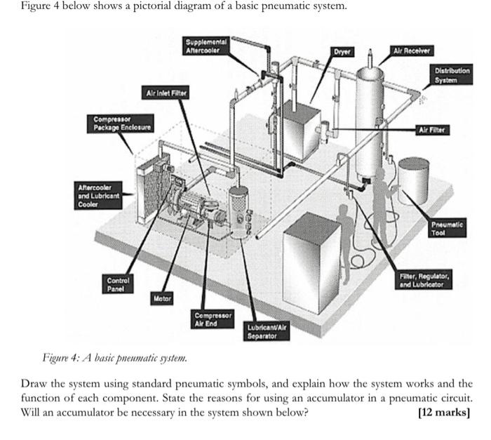
Solved Figure 4 below shows a pictorial diagram of a basic

Schematic diagram of the experimental procedure. (A) Schematic

PDF) Dynamic Interface Pressure Monitoring System for the

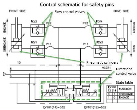
Pneumatic Schematics (Part 2 of 2)
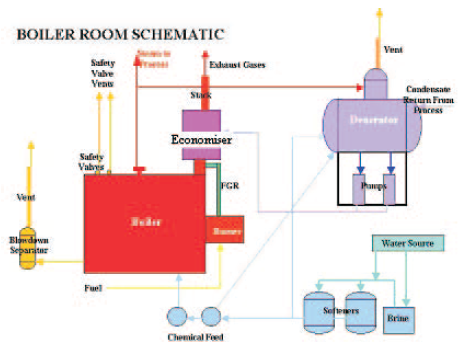
BOILERS

What Are Pneumatic Components? Working Principle & Function
Reading fluids circuit diagrams - pneumatic circuit examples

Shumi Zhao's research works National Institute of Biological

A programmable and self-adaptive dynamic pressure delivery and

15084 PDFs Review articles in VARICOSE ULCER
Related searches
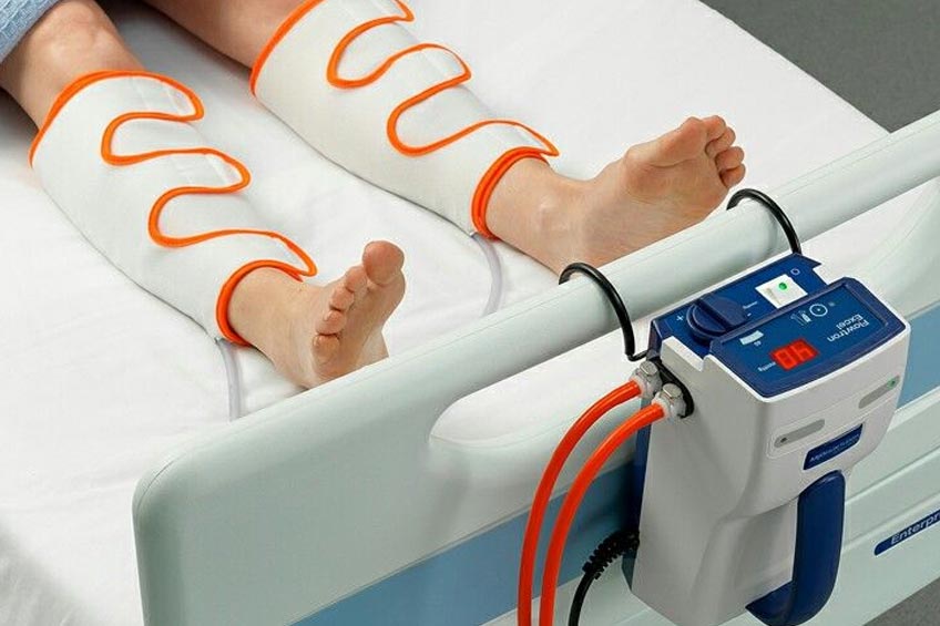
- Intermittent pneumatic compression therapy (IPC). The extremity to be

- Intermittent pneumatic compression

- Portable DVT Pumps Manufacturers in Ghaziabad, Best Portable DVT Pumps Suppliers Exporters Ghaziabad
- Pneumatic Compression - Om Physio Plus Nutrition & Yoga Therapy

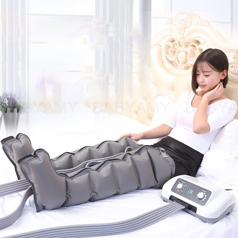
- Air Compression Leg Wraps Massager Circulation Leg Wraps


©2016-2024, slotxogame24hr.com, Inc. or its affiliates